
The Wells-Gardner K7000 is among the most common and easiest to fix of their monitors. Though not as durable as its predecessor the K4900, the K7000 is one of the best monitors you can learn how to fix. It does have a laundry list of things that can go wrong though, I’ll try to compile all the good ones I know.
Key areas to reflow solder:
Signal header
Yoke header
All ceramic resistors
R101, R89, R96, R103 and potentially R97, R98
Factory original flybacks from about 1987 to about 1991 (estimating) came with white adjustment knobs, later flybacks from about 1991-1997 came with black adjustment knobs. There’s a lot of hearsay surrounding the white knob variety about their rate of failure, but I can say after going through dozens of these that the OEM black knob ones fail more. Either will develop cracks around the Focus/Screen knobs. If your flyback is original always inspect the area around the Focus and Screen knobs on the transformer itself, if it’s significantly cracked, has poor adjustment range on Focus/Screen, or hisses and snarls at you… only then do I suggest flyback replacement. The OEM ones when working do still work relatively well and ironically are of better build quality.
The solder to R101 will practically dissolve from the heat output of this resistor. You may also experience lifted/severed solder pads in this area, especially on the C57 side. I strongly suggest mandatory reflowing of this part and also pay attention to R89, R96, and R103.
B+ testing is handled at R301 (ceramic resistor mounted on left side of chassis). The blue side facing you is the regulated B+ voltage, while the pink side closest to the tube is unregulated B+. Normal regulated B+ readings are 123V (19″) or 130V (25″). If you find 150-160V here, voltage regulator IC4 is most likely bad. You can determine this by disabling HV shutdown. This is achieved by desoldering an end of D10 out of circuit. If the monitor powers up you can suspect a bad voltage regulator IC4; if the monitor doesn’t power up look over all resistors mentioned above. R103 or R101, notably.
A blown fuse will be caused by shorted HOT (2SD1398, Q11), shorted bridge diodes D19-22, shorted degauss diodes D23-24, or shorted shutdown circuit D10. You must desolder ends of the diodes out for accurate testing. (They may read current both ways in circuit.)
Here’s some assorted K7000 life hacks.
When servicing a K7000 with a remote board, do yourself a favor and unplug the remote board and set it in a safe spot far away from where you’re working. The ceramic potentiometers are extremely fragile and can break if you so much as look at them wrong. If you skip this step, it can wind up looking like this!

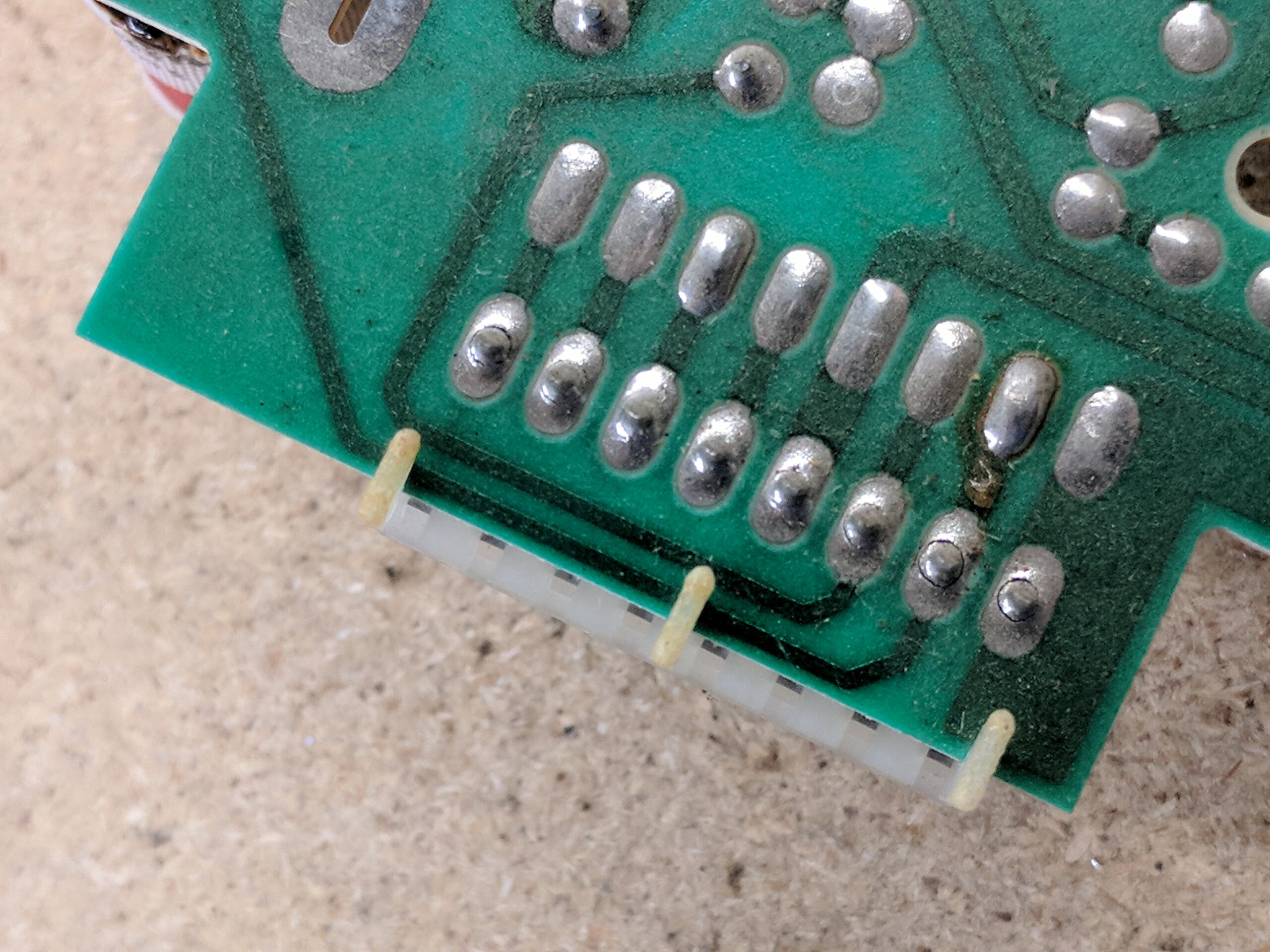
The following can happen to any monitor and should be among the necessary areas to address. The signal header pin solder takes a lot of abuse from years of plugging and unplugging to the point the solder will crack. This may result in dropped colors, non-existent sync, or perhaps even a blank screen. Here’s what it can look like.

I had a K7000 with one of the add-on cards with a jittery picture up and down. I apparently completely overlooked the solder on the card itself, you can see where it’s cracked at the plug here. These cards can either plug in or they’re soldered in. If you have the soldered in variety I encourage desoldering it out and reflowing the solder at the pins there too.
Examples of some of the add-on cards. Some are for some kind of power management and others for vertical deflection. The top one plugs in, the bottom one is soldered in.


Dirty K7000 I washed in the sink. A proper before and after.


===================
Wells-Gardner K7000
===================
C10 – 33uf 16v
C11 – 22uf 25v
C12 – 1uf 50v
C13 – 22uf 25v
C18 – 1uf 50v
C20 – 10uf 25v
C21 – 10uf 25v
C22 – 1uf 50v
C23 – 47uf 25v
C40 – 2200uf 35v
C42 – 1000uf 16v
C45 – 470uf 16v
C46 – 470uf 16v
C48 – 100uf 35v
C50 – 1000uf 25v
C56 – 22uf 160v
C57 – 47uf 160v
C204 – 4.7uf 250v (Found on some neckboards)
Compiled by Modessitt
Provided by www.juniorsrevenge.com