DISCLAIMER: I used a radical and different method to anchoring the neckboard transistors by bending the legs 90 degrees (seen in Step 4) that I no longer use as I discovered Wells-Gardner just didn’t install the transistors into the board as far as they could. I suggest desoldering the transistors fully and push them further into the board and soldering and this should be sufficient in most applications. Permitting the trace integrity is good, the transistors shouldn’t flex. If you have lifting traces however and the solder pads are intact, you can use the 90 degree method; just be mindful it will be very difficult if you have to remove the transistors again later. This method is mainly for the purple heatsink variety as they didn’t dissipate heat well and you may have issues with colors dropping out due to open traces in the drive circuitry. The silver heatsinks on later model K7400/7500 shouldn’t have the heat dissipation issues, but I’ve found they don’t anchor very well at all as they mount too high on the transistors and don’t anchor against the board very well. With that being said… read on.
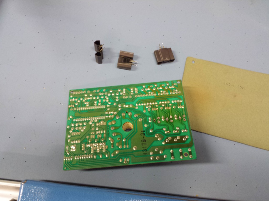
This neckboard design was used on the Wells-Gardner models U2000 (standard resolution), U5000 (standard/medium resolution switchable), K7400 (standard resolution), and K7500 (medium resolution). The heatsinks on the color drive transistors vary depending on when it was produced. Later models use thin silver heatsinks while older models use fatter purple heatsinks. The older purple heatsinks didn’t dissipate heat well enough however, and it’s common for the solder pads and even traces to lift from the extreme heat. This guide will at least show you some preventative maintenance tips for preventing or at least minimizing this symptom.
This may or may not alleviate any missing primary colors as well. If the solder pads have been severed from the traces you will have to patch the breaks in order to restore the neckboard to full operation again. I’ll try to provide a visual aid for how I (crudely) did that.
Also worth noting, for the process on the neck transistors, you can do that on any monitor chassis, not just U2000, U5000, K7400 and K7500. In fact, I strongly encourage doing it if you have a Hantarex Polo, cause even though those heatsinks have mounting pins you can solder in, they frequently break out and if the heatsinks touch each other, it will blow out the resistor for the blanking circuit. This method will eliminate any flexing of the neck transistors to prevent solder pad lifting or breaks in solder joints.
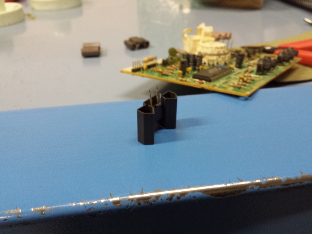
Step 1: Remove all 3 transistors.
Step 2: While you have the transistors out, straighten the outer legs flat and bend the middle leg accordingly to line up with the holes again. (This is if they have flexed significantly and are twisted badly.)
Step 2.5: If the solder pads are gummed up with a lot of flux, grab an old toothbrush and some 91% (or higher) isopropyl alcohol and clean them up first. (Not pictured, sorry.)
Step 3: Reinstall transistor. (Don’t solder yet.)

Step 4: Bend the outer legs completely flat (I suppose back when I did this years ago, a flathead screwdriver worked great) toward the right, and the middle leg toward the left.

Step 5: Solder. Snip excess leg off if overlapping traces if you have missing solder mask and are concerned about shorts.
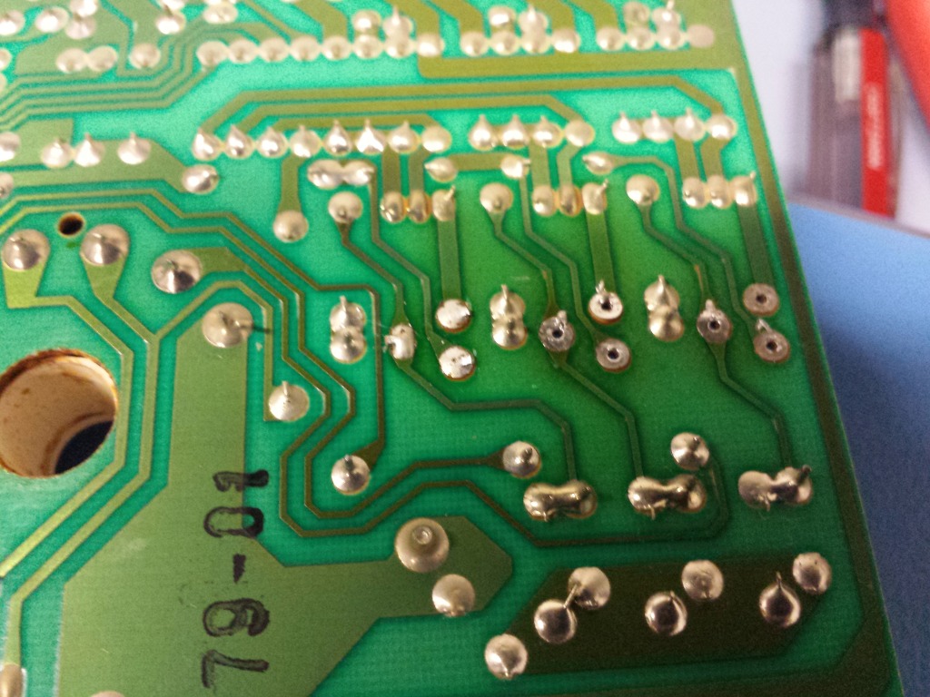
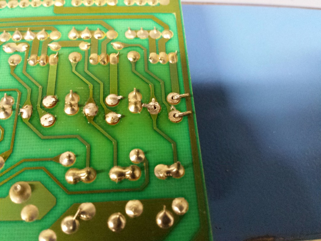
[Not really a] Step 6: Here’s an example of a lifted solder pad.

(Despite the DISCLAIMER posted at the top, this is an instance where the 90 degree method may help!)
Step 7: Flatten the lifted solder pad first, then bend the legs accordingly like done on the first transistor.

Step 8: Solder. The bending the legs approach will tack down the lifted pad into place. It won’t move anymore now. (Don’t forget to trim the legs.) Install the 3rd transistor next.
Step 9: Solder the last transistor in. Now that you’ve freshly reinstalled all the transistors, you shouldn’t have anymore issues with lifting solder pads, traces, transistor flexing or missing primary colors. You should now do a diode test between all 3 legs and their next points (before and after) in the circuit to verify the integrity of the pads/traces. If any of these read open, you will have to patch the breaks with wire.

Step 10: Try to straighten out and space out the large resistors accordingly. (EDITOR’S NOTE: I’ve taken to spacing these resistors out as leaving them in uniform order is what produces the excess heat! If you find your monitor has boiling rice aroma, try spacing them out so the heat isn’t cascading anymore.)
Before:

After:

I acknowledge it doesn’t look very nice but I’ve noticed this reduces the temperature a fair amount and will prevent any further damage or mishaps.
Step 11?: If you notice an abundance of Wincap caps on your chassis, you have original caps and it’s time for a cap kit.

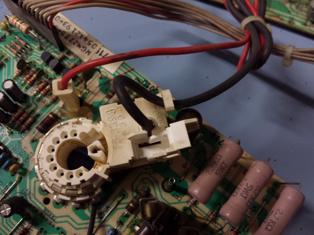
Step 12: Reinstall the chassis. For this I actually disconnected the neckboard entirely. The fatter black wire coming out the top of the flyback is the focus wire.

Step 13: Open the door (if it’s not open already, pull the clip on the side and lift up) and insert the focus wire inside the socket. (EDITOR’S NOTE: I had a K7400 last year I took out for servicing and had difficulties getting the focus wire back in; the conductive clip it sandwiches into was bent too tight and required opening the whole top cover of the socket to fix!) The thinner red wire coming out the bottom of the flyback goes to the G2 pin next to the neck socket. (EDITOR’S NOTE [again], if using a replacement flyback I personally desolder the G2 pin out of the neckboard and solder the new flyback G2 wire in directly.) Also don’t forget to reconnect the ribbon cable back to the deflection board.

Step 14: Fold the wire under the retaining clip.
Step 15: Close the door. Focus wire installed. When reattaching the neckboard to the CRT neck be certain you reconnect the CRT ground for the safety of all parties involved.

Step 16: Certain model K7500s (probably K7400s as well) will have the 3rd transistor mounted externally to another heatsink in the corner of the deflection board frame (most likely for improved heat dissipation, this transistor performs some kind of horizontal width control because the screen won’t fill out all the way if it’s unplugged). It will be connected with this cable.

Step 17: Plugging the cable in. it’s probably very easy to plug this in backwards, in which case, I don’t really know the ramifications of doing so. But the orientation left-right is white, red, black. (EDITOR’S NOTE: I’m fairly certain at some point before I produced this guide I have installed those backwards and it didn’t kill them.)

Step 18: As a bonus, an important safety tip on how I reinstall the anode cup. If you touch only the rubber you won’t ever get shocked. These generation monitors will self discharge with OEM flybacks for sure but there may be some aftermarket varieties that don’t, so exercise the practice of discharging the anode multiple times.

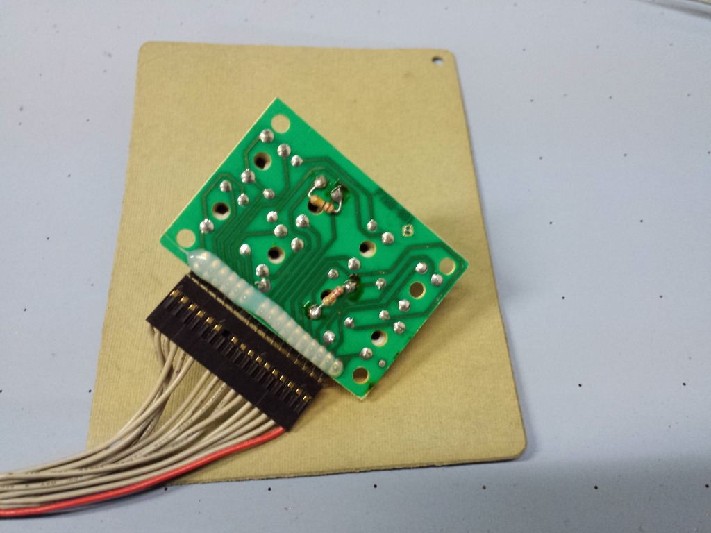
[Not really a] Step 19: this particular remote board has resistors going through some of the adjustment pots. thought that was interesting.
The final detail is reconnecting the yoke plugs to their headers. The horizontal pair goes to the pins in the middle of the chassis (the red/blue plug) and normally the red wire will face you. The vertical pair goes to the pins near the vertical IC on the right side of the deflection board, (the yellow/green plug) and in most every instance the yellow wire was on the leftmost pin. Some yokes may have a brown wire instead of green, they perform the same exact function.