Foreword:
I originally wrote “The Essential PSU Guide” back in 2011 and have shared it with dozens of people over the years. I’ve reached a point where in its unmodified form since then that I may be doing the community a disservice, so I’ve chosen to revise it after I’ve experienced fixing another 1000 games since then. Some of my terminology needed updating, and maybe it needed to be a little more simplified.
Introduction:
Arcade video game hardware is powered by DC voltages that are output from a power supply unit (PSU). There are many different brands of power supplies on the market, but for my exercise I will be using Happ PowerPro and the original U-San Peter Chous as a demonstration. According to legend, the Peter Chou variety is the original in which the PowerPro is based off of. Despite any similarities they may have though, they’re still very much different. This becomes more complicated when you use cheaper off-brand models, which I will explain why you want to avoid using them later on.
Depending on the form factor of power supply you’re using the output voltages may vary slightly. Here are different types of power supplies available:
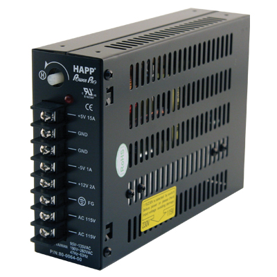
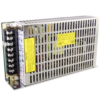
Happ PowerPro (115W)
The relatively standard screw terminal model.
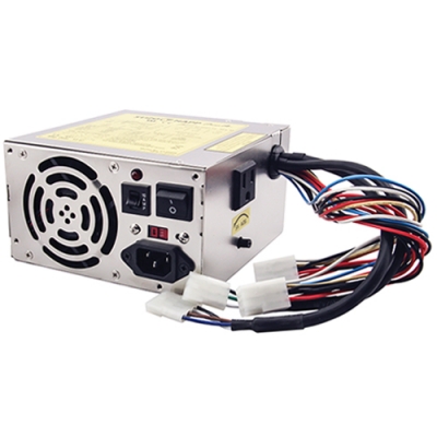
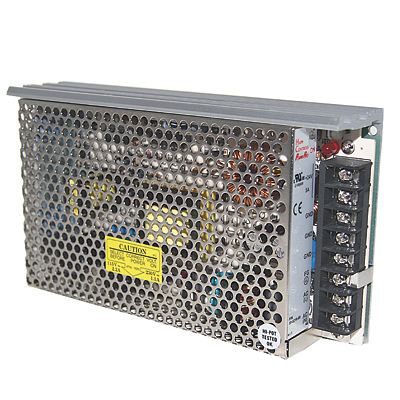
Happ PowerPro (200W, AT Form Factor)
Happ’s “box” power supply with 9 pin molex plugs.
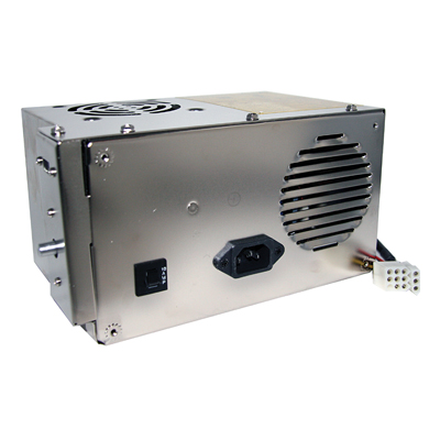
Happ PowerPro (150W, XT Form Factor, Internal Power Switch)
Happ’s “Ultimate” power supply, commonly found in Dynamo and other kit cabinets with built-in power switch. (Typically accessible through a hole in the side of the cabinet.)
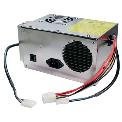
Happ PowerPro (150W, XT Form Factor, External Power Switch)
Happ’s “Ultimate” power supply, commonly found in Konami, Neo Geo, and other kit cabinets with external power switch plug. (The cabinet power switch plugs into this.)
Happ PowerPro (120W, +12V ONLY)
Power supply used in applications where the game uses +12V exclusively. (More elaborate explanation to be seen later.)
Happ PowerPro (120W, +24V ONLY)
Power supply commonly used for powering flat panel displays powered by +24V instead of AC.
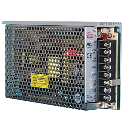
Happ PowerPro (130W)
Another more industrial variety of the familiar black screw terminal model. These are often found mated to some Arcadeshop power supply conversion kits due to their higher wattage and amperage outputs for some applications.
Let’s go back to the +12V only 120W PowerPro real quick. Other power supplies that output +5V in any capacity use the 5 volt supply as the base voltage. A load must be present on the +5V line or else you can potentially damage the power supply, which effectively means a game board or some piece of hardware needs to be connected that requires 5 volts to operate. I’ve observed on accident a few times that the PowerPro may have a shutoff feature built in where it will shut the power supply down if no load is present after a certain period of time. As to the +12 only model though, there are many redemption games that are powered exclusively off 12 volts, so running a normal power supply on these would not be a good idea since there would be no load for the 5 volt supply. (I conveniently never mentioned this previously!)
Operation:
Many chips on game logic boards are of TTL or CMOS variety, but custom chips also work the same way. TTL logic (or, the chips) have an operating tolerance of 4.75V to 5.25V. What this means is your game may malfunction if the voltage goes below 4.75V, and logic chips could be damaged if you go above 5.25V. Some older model Happ Controls (see: pre-Suzo-Happ) have an LED to indicate if the +5V output is too high or too low. I strongly encourage not following this as I will demonstrate how to test voltage accurately at game logic. +5V is adjustable on video game power supplies for reasons such as the type or length or wiring varies between games and the voltage needs of different circuit boards will also vary. The adjustment enables you to fine tune to the game you’re running as needed. Depending on the hardware, +12V and -5V (or -12V) may also be needed for certain chips on the board, but in a majority of applications +12V will only be for audio amplifiers and in some games both vintage from the 80s and newer from the 90s may use -5V or -12V for audio as well. I also figure now would be a good time to mention some power supplies will not refer to ground as GND, or logic ground, but rather as COMMON. All grounds are connected, so that’s what COMMON or COM are implying.
One of the foremost lessons I learned when I was trained in how to fix games was there is no such thing as a wiring color standard with games. To cite some examples, Williams used solid grey for +5, Atari used brown for ground, Midway and Nintendo used whatever they wanted, and Sega really complicated things by using yellow for +5 and white for ground. **IMPORTANT** So I encourage that you obtain the service manual that pertains to the game you’re working on which you can find most any of at http://arcarc.xmission.com/. If you’re unable to find a manual and need additional help please PM me on KLOV @mecha or e-mail me.
Common wire color configurations will be red for +5V, yellow for +12V, and black for ground. Most any Japanese JAMMA games will only use 5 and 12 volts; the -5V contacts at the JAMMA edge will often just be dummied out so they don’t go anywhere. Hacky technicians will cut the -5V wiring out of the harness, or for a great example my Total Carnage didn’t have -5V wired because the sound board for Total Carnage didn’t use it — but when I added Smash TV to the cabinet I needed it!
Williams classic colors were solid grey for +5V, grey-yellow or grey-white for regulated/unregulated +12V, solid orange for -5V, grey-green for unregulated -12V, and black for ground. A variation of this color scheme existed from 1988-1993 with solid grey for +5V, grey-yellow for +12V, grey-green for -5V, and black for ground.
later Williams (or new Midway) wiring colors from Mortal Kombat II onwards were red for +5V, orange for +12V, yellow for -5V, and black for ground. Many people have screwed up and connected the yellow -5V wires for +12V thinking that yellow is automatically +12V and wound up nuking their sound boards as a result.
**IMPORTANT** To reiterate once more, if you’re uncertain, please look in the service manual of the game your cabinet is or was… or ask me for help. I likewise may convert this into an easier to understand graphic later and extend to other makes like Sega and Atari.
Measurement:
Finally some action, huh? Instinctively if you’re new to this sort of thing you may think logically that you could measure the voltage at the power supply itself, adjust accordingly, and be done. If only it were that easy… I already touched on wire types and lengths; in the pre-JAMMA era the game manufacturers engineered the games in whichever way they wanted. There was almost no instance of games from different manufacturers that would be pin compatible in any way. Some would use 22 gauge wire, some 18, some 16. Some would be very generous with the amount of wire, and then there were others like Konami where there was only one ground wire going back to the power supply. I’m not going to provide an electronics workshop, there’s plenty of resources online to learn about this, but just keep it in the back of your mind.
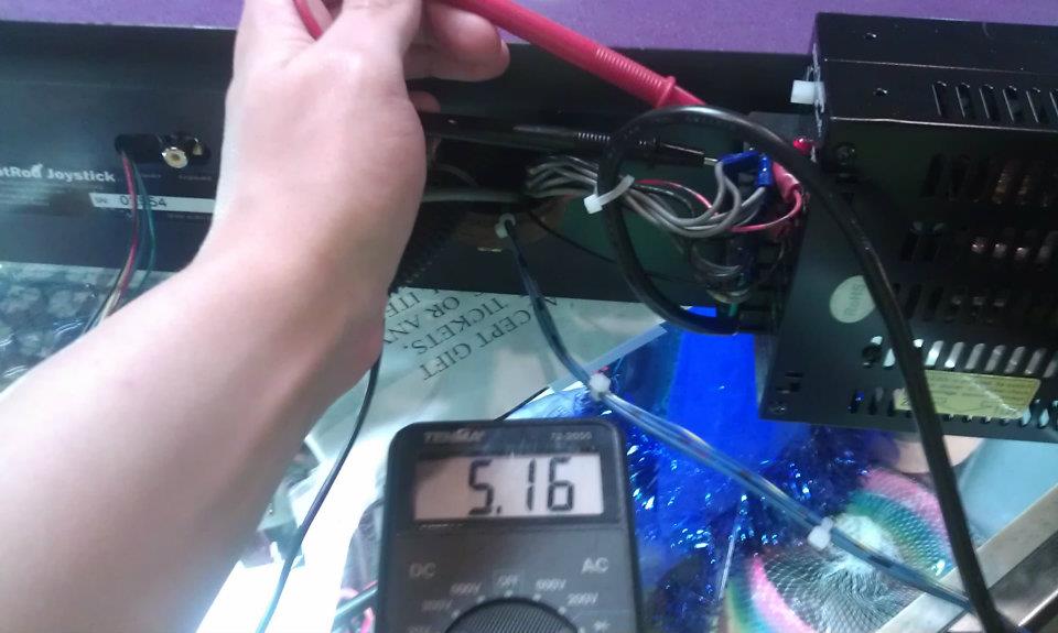
Some games may have test points for checking +5V/ground, but an even better means for accurately testing your voltage as it is getting to the game board is at one of the TTL chips itself.
Pictured below is what I’m guessing was a picture of a ROM, but I suggest using one of the other 74 TTL chips for this instead. (Some ROMs will have unusual pinouts I learned over the years.) The corners are labeled accordingly, and even color coordinated, as to what they are.

Although I strongly suggest performing this test with steady hands, if you were to slip and bridge +5V or ground to the adjacent pin it shouldn’t destroy anything — but if you’re dealing with a tri-voltage chip like 4116 RAM in an old Williams game, you could do damage bridging +12V or -5V to another pin. (I strongly discourage testing at tri-voltage chips for this reason.) Observing the U-shaped notch of the chip, the lower right corner will be ground, and the upper left will be +5.
I have a pictorial demonstration of how the voltage will drop from the power supply, to the JAMMA edge, to the chips. I used a Midway Seattle Blitz ’99, just to prove to the world they’re not the power hogs they’ve been long purported to be. And this is with a lower grade PowerPro attached to my supergun, not the higher wattage AT style unit the games used.
At the power supply lugs:
At the JAMMA edge:

At the logic (or in this case, the sound rom on an NFL Blitz ’99):

Box style power supplies like the 150W or 200W you will measure voltage at the red and black wires of the 9 pin molex plug to get your source voltage. (Actually pictured was a 12 pin plug, I think this was a Cruis’n World.)

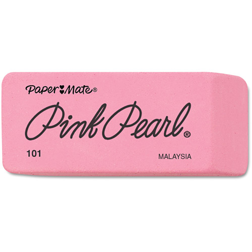
If you’re noticing a substantial drop in voltage between the power supply and the chips on the game board, you may have a dirty JAMMA edge. If you’re dealing with an older game with .156 header pins and plugs, you may have a larger issue that will be addressed at a later date. You don’t necessarily need an expensive can of DeOxit to clean the JAMMA edge, just use a higher grade pencil eraser like a Pink Pearl (pictured) and just erase against the contacts of the JAMMA edge until the dark tips (where the edge connector, or erroneously called the “harness” plugs in at) are cleaned off.
The most misleadingly useful tool you might have:
If your power supply voltage was turned way up before to accommodate this drop previously, I suggest turning it down first; I know I mentioned earlier you NEED a 5 volt load on the power supply, but you can run it for about 10 seconds with no load and nothing will break. Just make sure the on/off switch is in close proximity.
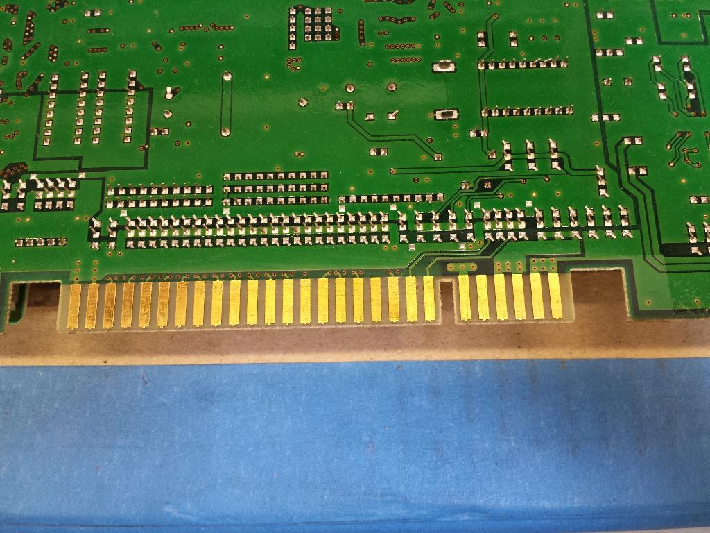
A pictorial demonstration of before and after of cleaning a JAMMA edge. (I believe this was a Capcom CPS2 A board, probably my old Street Fighter Alpha 2)
Really dirty edge connector:

Much cleaner edge connector:
A Real Time Demonstration of What Cleaning a JAMMA Edge Will Do:
Observe the voltage being a little low:
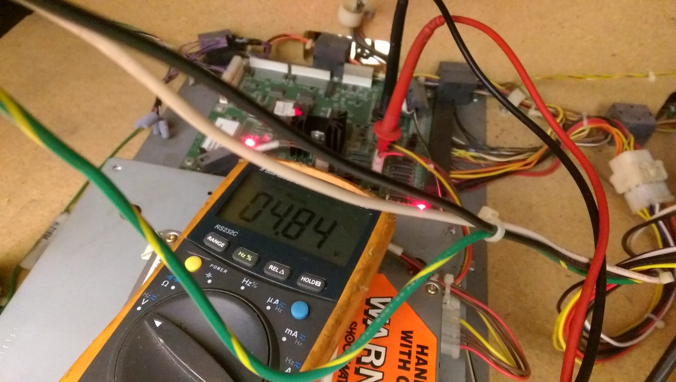
Clean the JAMMA edge with the pencil eraser:

Profit:

Pretty cool, right? An added engineering bonus on the demonstrated Area 51 Site 4:

Many people will not address the issues of a voltage drop and will simply turn the +5V adjustment way up to reach 5 volts or whichever voltage they’re trying to achieve. The larger the differential between the power supply and game board the higher the presence of resistance there will be. This is how you start burning up the edges on boards. So if you have a dirty edge, or a poor grade JAMMA harness like the Chinese ones that have fake thick gauge wires (cut and strip one to see, half of the wire is the insulator!) then you may entertain replacing the entire harness with a better one instead.
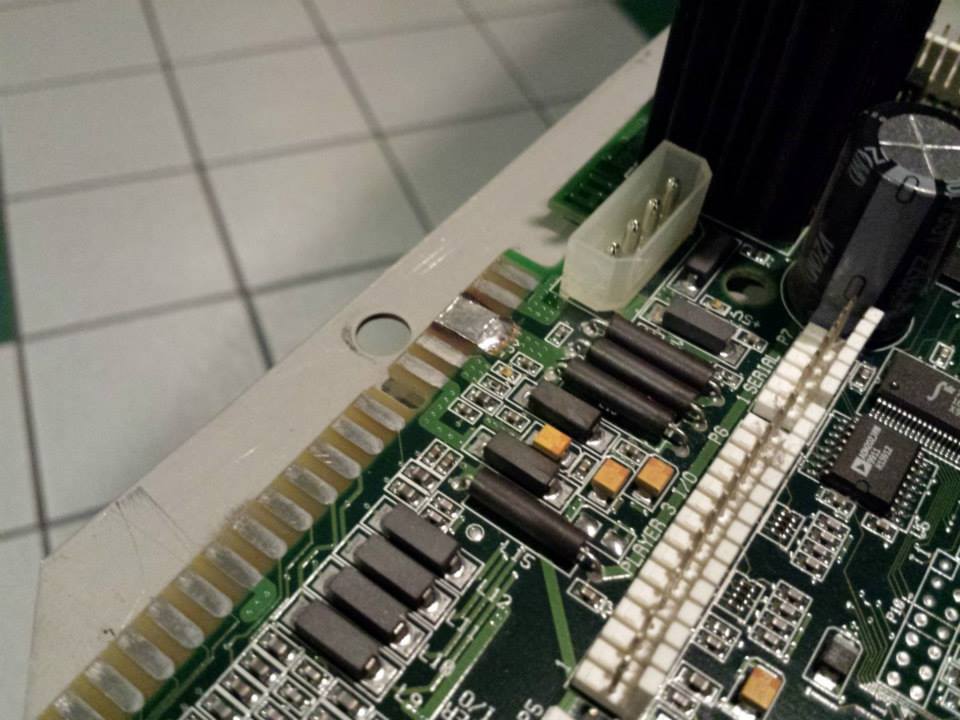
A pictorial demonstration of a San Francisco Rush 2049 edge with repaired burned up +5V contacts I saw on route when I worked for Namco years ago. (See my chart below for suggested operating voltages for hardware types.)

Sega:
It only figures Sega get their own section; a large reason for this however is because they use a very different color scheme for their power wiring. (This section is mostly unchanged from the previous version of this guide.)
So as for those sophisticated and newer Japanese makes, I will talk about Sega’s hardware. While this can pertain to NAOMI, NAOMI 2, Chihiro, Triforce, Sammy Atomiswave (which is a variation of the NAOMI that will use “standard” JAMMA colored wiring), I will speak of it as NAOMI in the instructions.
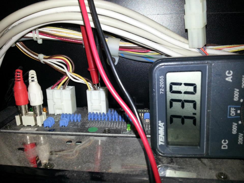
First of all, Sega uses an entirely different color scheme on their wiring. +5V: yellow, +12V: red, +3.3V: brown, ground: white. There are other games produced by Namco that use Sega hardware that will use more conventional wiring colors like those mentioned earlier in this guide.
The Sega NAOMI (or more specifically its game or DIMM cartridges) is a very voltage-sensitive piece of hardware. It’s generally frowned upon to operate them above 5.10V, and the +3.3V line should be adjusted to 3.30V exact. These you won’t have to open up and test at the chips however, you can simply get away with metering at the plugs on the back of the boards (applies to all hardware types listed in this section). I’ve seen sharp voltage drops in Namco games like Maximum Tune and Mario Kart GP, so be certain you don’t measure at the power supply and do it at the board, otherwise if the +3.3V line is set too low the game will not boot.
Measure +5V at the yellow (+5V) and white (ground) wires on Sega hardware. (Namco cabinets will use red for +5V and black for ground.)

Measure +3.3V at the brown (+3.3V) and white (ground) wires on Sega hardware. (I think it’s yellow on Namco cabinets)
Suggested operating voltages for hardware types:
Mortal Kombat (T-unit)
I performed very extensive testing on this game both with my board at home and a game at work. With the power supply set to 5.10V I observed that both games would reset when you got to Goro. Not entirely sure what that was about, but I found running the game at 4.95V to the chips was the most reliable configuration.
Terminator 2: Judgment Day (Y-unit)
Much like the T-unit version of Mortal Kombat I had issues with resets on Terminator 2. Likewise it needed to be dropped to 4.95V to ensure reliable operation. I don’t understand how two different hardware platforms have this problem or why one of each games do it and none of the others.
Sega NAOMI/Triforce/Chihiro and other Sega platforms that use cartridges
The conventional wisdom with the Sega NAOMI is not to run the +5 above 5.10V. There are highly voltage sensitive buffer chips on the cartridges (both the game and DIMM variety) that will burn out if you run the power supply too high. Anything between 4.95-5.05V is sufficient, I always ran them at 5.00V though.
Midway/Atari Vegas/Durango
I suspect the issue with the Vegas and Durango platforms has to do with the circuitry that produces +3.3V to power the CPU. If you feed too much +5 into the JAMMA edge it will fry the +5 fingers. Not exactly the end of the universe if this happens, my Sportstation had this out of the box and I didn’t realize the importance of things like resistance or heat then, but I eventually fixed the problem with copper tape several years later!
This has been a long time in the making, if I think of any other useful additions to make I will add them later.