I made this into an exercise when I was servicing a K7400 monitor a couple months back. these are all the solder points that I clean up on this generation of Wells-Gardner monitors because as you can see in the pictures the factory solder looks pretty janky. if you’re new to servicing monitors my very basic bit of knowledge to share is that any area where you plug and unplug stuff will introduce stress on those header pin solder joints and the factory solder will eventually break. you’ll observe in these pictures that the surface of the solder in some of them looks like concrete, or in other instances it will be gold (“carmelized” as Chad Entringer of Arcadecup calls it) and in either instance it’s a sign of high heat. as the solder diminishes more with regular operation it will create an exponential failure scenario where it will get worse as resistance increases, resulting in more heat!

flyback pins: so worth noting, I always desolder flybacks off deflection boards (or “chassis”, as we routinely refer to them as) because a) it makes handling the board a lot easier b) you don’t risk banging the flyback on the table surface and physically break it and c) the solder is often poor and needs to be redone anyway. if you work on a lot of K7000s you’ll find those get really tore up, and they were the influence behind why I have done this the last 8 years or so. the Suzo-Happ cap kits I used to use actually instructed resoldering the “high voltage unit”, so that was the inspiration.

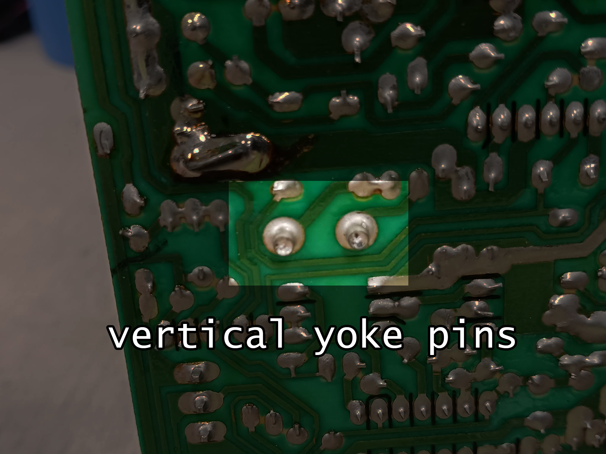
the yoke headers: a lot of current circulates through these so it’s pretty customary the solder here will diminish. this is something you should do on all monitor models, and it’s baffling to me how many monitors I’ve had to fix that were professionally serviced previously where this was avoided. if either of these has some halo-ed pins (meaning the pins have a chunk of solder broken off from the rest of the joint) you’ll get either horizontal or vertical collapse. though in fairness to these models, I suppose I’ve never seen that happen before. (yet?) I apply solder in a circular motion around the pins to flow it through fully. exercise caution when melting solder here as it’s entirely normal for the pins to back out of the board, and take your time between the two pins, don’t melt them both one after the other or the whole header strip will fall out. if you have a loose yoke handy, plug it in before doing this.
![]()
the yellow transformer and its diodes: from the words of the great Randy Fromm, there’s a whole circuit on monitors that turns 120V AC into DC (that’s the bridge rectifier, 4 diodes) but then it gets to this transformer and its outputs are AC again. if ever you wondered why these monitors with their 3 pin power plugs don’t require isolation transformers, it’s because this yellow transformer is the isolation transformer. if you were to poke and prod one of these with an oscilloscope however, you will need a traditional isolation transformer (as the power supply and deflection sections are not meant to be crossed… for yours and its safety). as you could surmise, this section takes a fair amount of abuse, especially on the older U5000 and U2000 models. I add solder to all these points and remove it with preferably a tool like the Hakko FR-301, and then go over all the components with Dremel wire brush. you’ll get significantly better results with flowing the solder through correctly this way.

signal header pins: here it is, the area that most commonly will have solder break. it makes sense, with all the monitor swaps that were conducted back in the coin drop days where it was imperative that the highest earning games always be running… and well, the signal plugs have to get connected and disconnected with these swaps. I have better examples of the halo-ing of signal header pins, but to be consistent I stuck with the same deflection board for all these examples. you can see some of the cracks beginning to form. here you only really need to add more solder cause this is a low current area, but the pins are relatively close together and you run the risk of bridging. it’s a good opportunity to practice de-bridging!
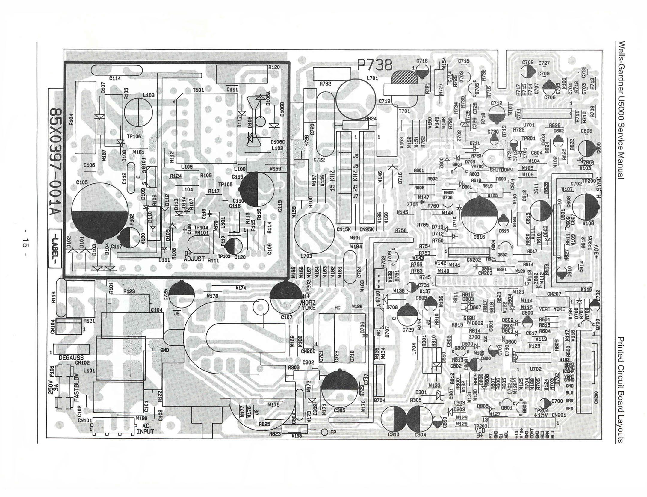
in closing, if you have a U5000 or U2000 chassis I encourage popping by my Monitors -> U5000 page and consult the NFL Blitz HOT service bulletin for a list of problem parts to inspect. these have a lot of resistors that go out of tolerance, like R100, R104, R728, or R760 for examples. if you follow my instructions on this page along with installing a cap kit your monitor should work pretty well for awhile then.